Decentralised technologies interest me greatly. A sub-section of this genre is decentralised storage, which got its first mass debut with Napster. Napster was a “hybrid” model in that it used servers to coordinate peers… but not long after Napster other peer-2-peer services came along, like Kazaa, Kademlia (the basis for a myriad of p2p services), BitTorrent and very recently the boldly named InterPlantaryFileSystem RAWR. None of these protocols support monetisation. They are embodiments of the sharing economy.
More recently, companies have tried to produce decentralised storage systems which do monetise data storage. The big recent names have been Sia, Ubbey and Storj, with perhaps Urbit hanging around in the background. All of these fledgling systems have had major issues associated with them, which is an interesting discussion in itself. I’ve experimented with at least Sia and Ubbey previously.
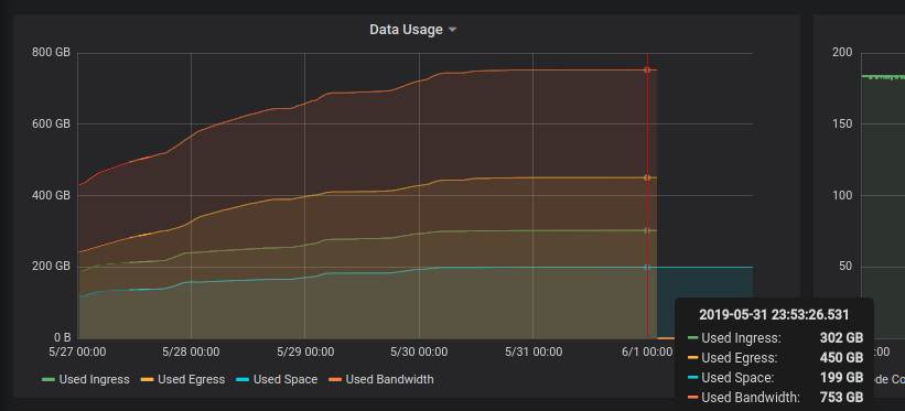
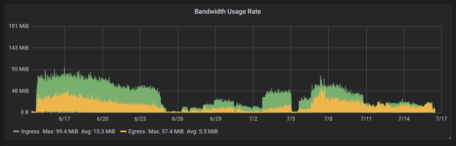
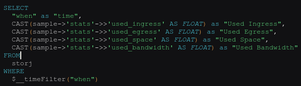
Storj recently announced that they were going to completely overhaul their network based on lessons learnt from their current system (v2) and asked for testers for their new system. I signed up and so far their software has been stable. I’ve written a small app which grabs telemetry from their daemon and inserts it into a Postgres database. Grafana is then used to graph this data.
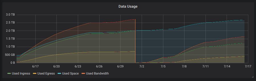
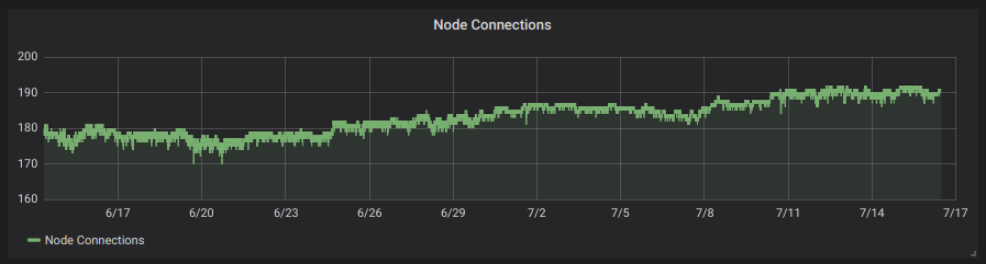
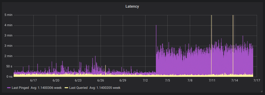
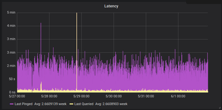
StorageNode data utilisation graphStorj Storage Node egress, ingress and storage utilisation over the course of a month.Node connections… is this the entire network ?Storj Storage Node “Latency”Bandwidth Usage
To get a small logging system going you’ll need to do this :
Launch a Postgres instance on your Docker-enabled machine :
docker run --restart=always -d -p 3000:3000 --name=grafana -v /home/yourhome/grafana-data:/var/lib/grafana --link storj-pg:storj-pg grafana/grafana
# You can also use a network to link these machines, which is the new way of doing things and is a fair bit sexier than the "link" directive.
and then launch my app (to generate the initial config) :
docker run -ti --rm --detach=false -v /home/yourhome/telemetryconfig:/config aquarat/storj-postgres-logger:0.3a app -configfile=/config/config.json
My app will create a config file in the host directory, which you will need to modify to suit your installation. Once that’s done, relaunch it to check it works :
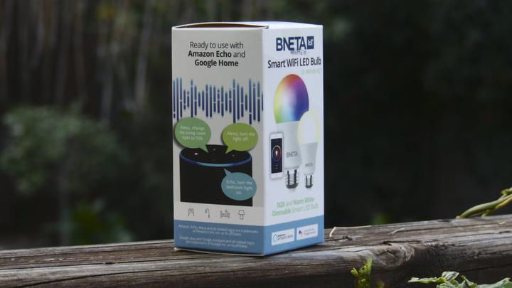
Sonoff smart devices tout various features, all accessible through the “EWELink” app and “cloud” infrastructure (it looks super crap). Um, no, if it’s in my house and on my WiFi network it needs to run open source software (or at least be made by a trustworthy company subject to mass scrutiny – even that’s not ideal, but life’s full of trade-offs). Sonoff devices are of particular interest to me because they (1) run a well-known micro-controller that has a lot of community-driven software and support available, (2) they’re SUPER cheap [$1.50] and (3) they’re really versatile. I’m proud to say that although I own and operate more than 20x Sonoff smart devices I’ve never installed their Android app. Life’s too short for that.
I bought one Sonoff B1 R2 to test with… it was a ball-ache to programme it with custom firmware (Tasmota) but it was possible and it works well once flashed.
Flashing a Sonoff B1 R2 is far from great. I just want lights and colours, not soldering.
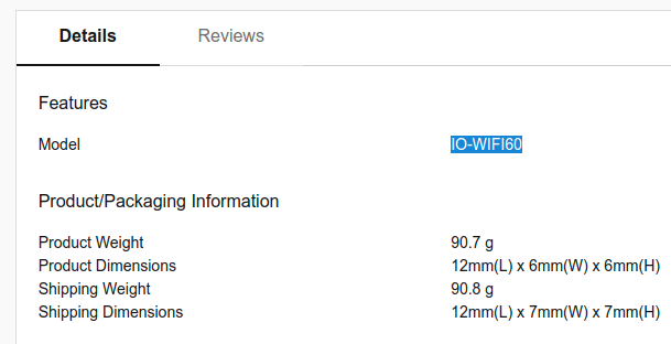
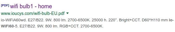
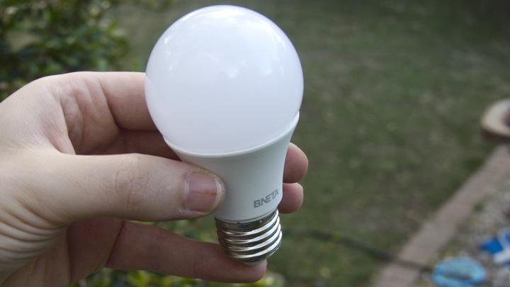
I recently came across an advert for a WiFi “Smart” LED light at a local mass retailer (ultimately owned by Walmart, known as Makro in South Africa). The LED light was branded by a local company but South African companies rarely produce anything original (sorry guys, we don’t, we should, I really wish we did). The light was on special too and a fair bit cheaper than the Sonoff. This was too tempting. I thought “what are the chances it’s just a rebranded Sonoff device ?”. The device has the same basic specs and power rating as the Sonoff B1. Googling for the device name only yielded the local company’s empty website, but searching for the product’s SKU “IO-WIFI60” revealed a link to a Chinese site.
Makro’s SKU
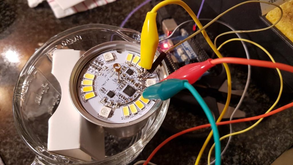
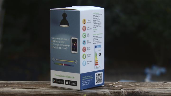
So yes, screw it, let’s give it a go. R 250 (about $19) later and we have this :
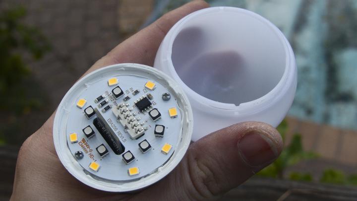
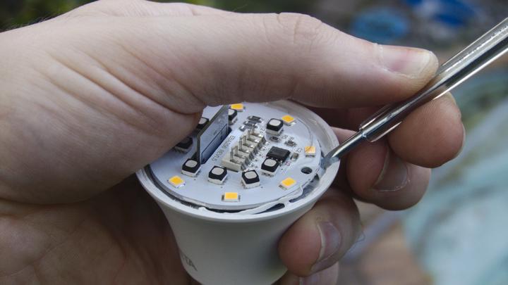
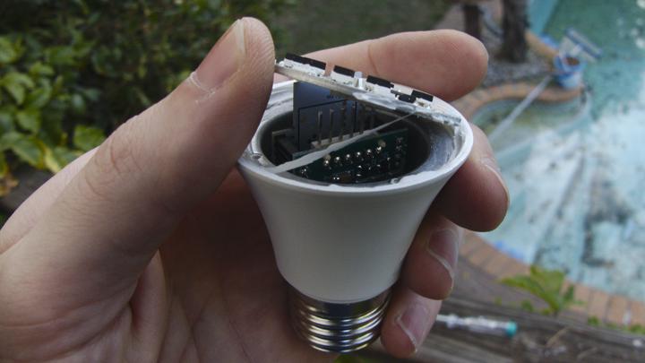
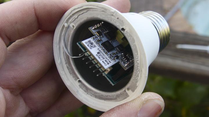
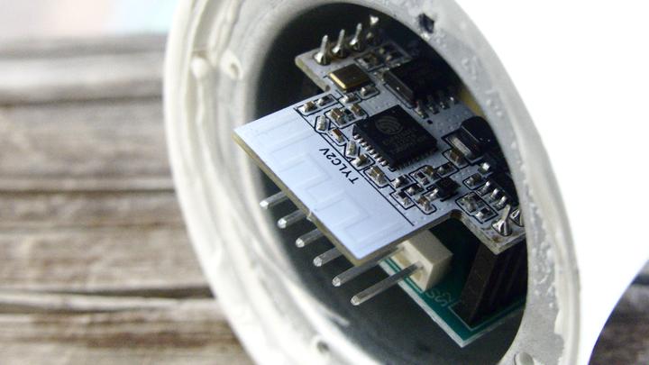
Yeah, I opened it up on the drive home 😀 Unlike the Sonoff, which either pops off or unscrews this light top has been glued on. The line on my thumb is from voting 😉I’m very excited at this point because that looks like an ESP8266 dev board WOOOOOHOOOOOScrews gone. The white stuff on top feels like silicone, but below it there’s thermal paste. I assume to bond the mostly copper top PCB to the alloy base. You can see a bit of the thermal paste going on there and what looks like a power supply PCB with the dev board riding on top of it. It’s essentially a DIP8 package. The board can’t be easily separated from the power supply PCB and the PSU PCB appears to be soldered to the base.And there’s the ESP8266 😄😄😄 along with what looks like a voltage regulator, clock source, etc. The bit sticking out is the PCB antenna. Once again, below the white board is a power supply PCB which runs down into the E27 fitting. At this point I didn’t know what the label/QR code/code meant.Label removed and ahhhh, a model number.
A quick Google search and…
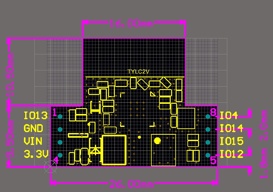
The module the MCU is on, as it turns out, is made by a company called Tuya. The label with a QR code on it that I removed is a key for Tuya’s cloud infrastructure. In short Tuya makes ready-to-go ESP8266 modules that are pre-flashed to work with their cloud infrastructure. The idea being that you point your users to a white label app branded with your logos, which configures the device via WiFi. As the manufacturing company (pffft) you buy several thousand pre-flashed/configured WiFi modules from Tuya and integrate them into your product. This is interesting but still problematic as I don’t want their firmware in my house haha. There are no easily-accessible pins to flash this device… maybe someone has hacked the OTA protocol.
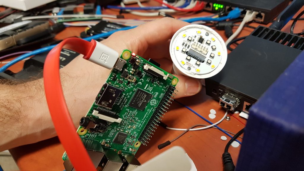
I can feel the excitement GROWING. Bring me the Pi!
Yes, that Pi will do. Hands ftw.
unzip 2019-04-08-raspbian-stretch-lite.zip
dd if=2019-04-08-raspbian-stretch-lite.img bs=64k of=/dev/sde status=progress
mount /dev/sde1 /mnt/sde
touch /mnt/sde/ssh
sync
umount /mnt/sde
<some time later>
# GO GO GO!
ssh [email protected]
sudo mount -o remount,async,commit=500,discard,noatime,nodiratime /
# ^ It's called living dangerously :D Speeeeeeeeeed
sudo apt update
sudo apt install byobu git
byobu
git clone https://github.com/ct-Open-Source/tuya-convert
cd tuya-convert
./install_prereq.sh
# You're not going fast enough :<
./start_flash.sh
Go go go!
pi@raspberrypi:~/tuya-convert$ ./start_flash.sh
~/tuya-convert/scripts ~/tuya-convert
======================================================
TUYA-CONVERT
https://github.com/ct-Open-Source/tuya-convert
TUYA-CONVERT was developed by Michael Steigerwald from the IT security company VTRUST (https://www.vtrust.de/) in collaboration with the techjournalists Merlin Schumacher, Pina Merkert, Andrijan Moecker and Jan Mahn at c't Magazine. (https://www.ct.de/)
======================================================
PLEASE READ THIS CAREFULLY!
======================================================
TUYA-CONVERT creates a fake update server environment for ESP8266/85 based tuya devices. It enables you to backup your devices firmware and upload an alternative one (e.g. ESPEasy, Tasmota, Espurna) without the need to open the device and solder a serial connection (OTA, Over-the-air).
Please make sure that you understand the consequences of flashing an alternative firmware, since you might lose functionality!
Flashing an alternative firmware can cause unexpected device behavior and/or render the device unusable. Be aware that you do use this software at YOUR OWN RISK! Please acknowledge that VTRUST and c't Magazine (or Heise Medien GmbH & Co. KG) CAN NOT be held accountable for ANY DAMAGE or LOSS OF FUNCTIONALITY by typing yes + Enter
yes
======================================================
Starting AP in a screen
Stopping any apache web server
Starting web server in a screen
Starting Mosquitto in a screen
======================================================
IMPORTANT
1. Connect any other device (a smartphone or something) to the WIFI vtrust-flash
The wpa-password is flashmeifyoucan
This step is IMPORTANT otherwise the smartconfig will not work!
2. Put your IoT device in autoconfig/smartconfig/pairing mode (LED will blink fast). This is usually done by pressing and holding the primary button of the device
3. Press ENTER to continue
======================================================
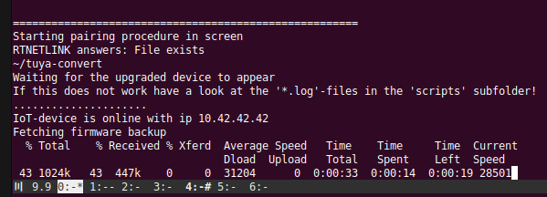
Starting pairing procedure in screen
RTNETLINK answers: File exists
~/tuya-convert
Waiting for the upgraded device to appear
If this does not work have a look at the '*.log'-files in the 'scripts' subfolder!
....................................................................................................................
Okay, so, that didn’t work. Tailing the log files indicates the device is present but rejected connection attempts. Probably a race condition. Let’s try again. Off, On Off On Off On… blinking fast. Here we go.
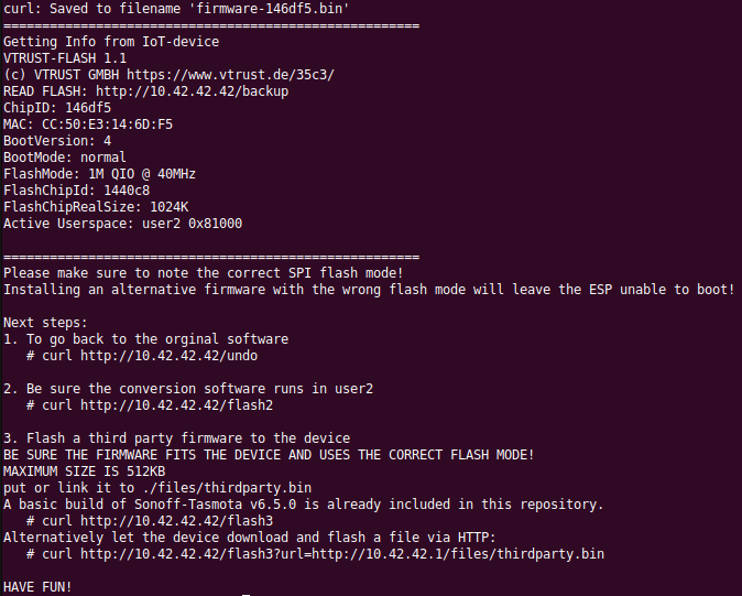
YesssssssThank you, I WILL HAVE FUN Merlin Schumacher, Pina Merkert, Andrijan Moecker and Jan Mahn. Did I mention they came up with this very slick project ? Thank you!
Target device retrieving the firmware during OTA 😀
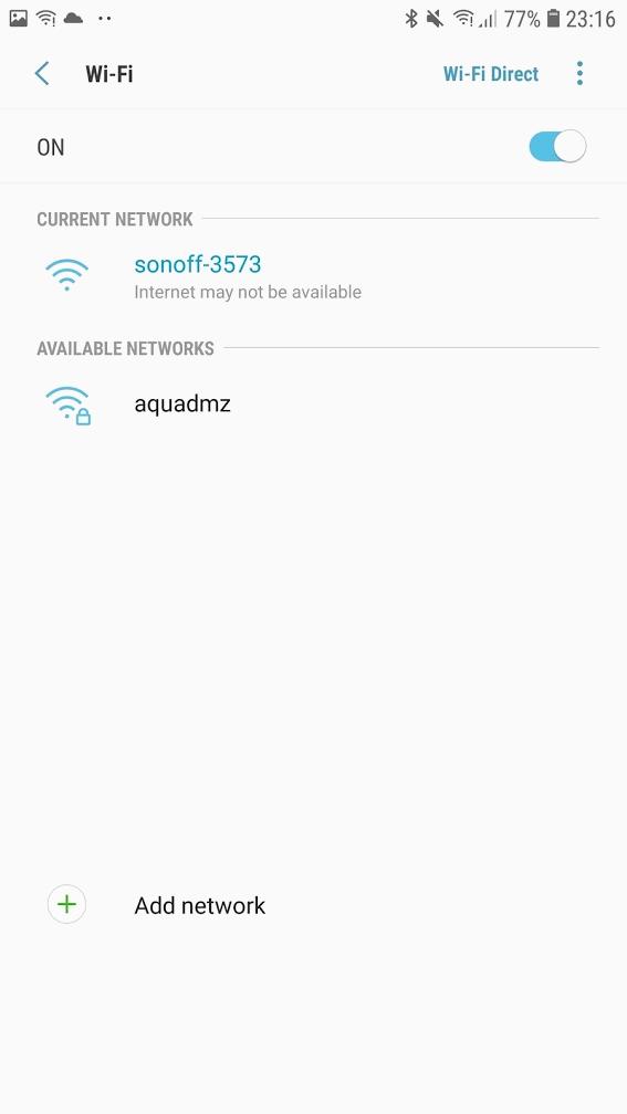
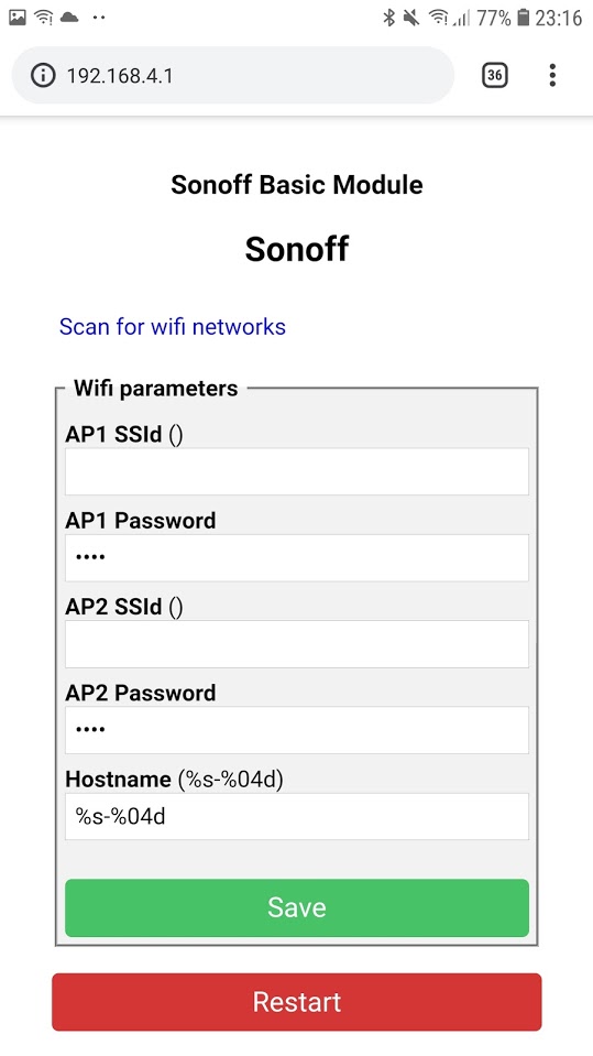
Go to your mobile phone and connect to the Tasmota-created network, then go to your phone’s browser and navigate to 192.168.4.1
Enter your wifi network’s SSID and password and click “Save”. Do this quickly, you have 3 minutes from boot to do it otherwise the device reboots.
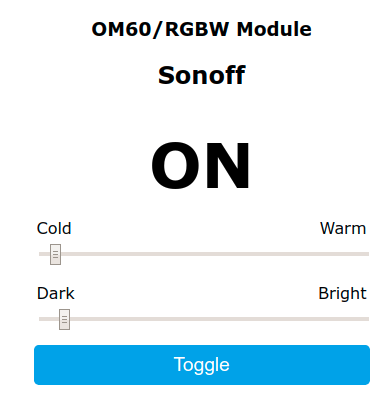
Okay, so at this point we have an ESP8266 running the base Tasmota firmware. The Tasmota firmware has different modules which allow it to manage different kinds of devices. There’s a big variety involved though, like dimmers, switches, temperature sensors, etc. So we need to be fairly specific about the kind of device we’re trying to control. I need a Tasmota “template”. I’m hoping something someone else has created will work with this device. Looking at this page one particular candidate stands out : (there’s that “60” again from the Makro SKU…)
The device is on my home network now, so I can configure it using my desktop machine’s browser yay.
Go to the device IP with a browser and click : Configuration -> Configure Other
So this is great, but now I want to get the device to talk to Home Assistant. To do that start by configuring the device name :
Configure -> Other : Set Friendly Name
Set your MQTT config to point to your HA system.
And then my favourite: go to the console and run the following :
Sleep 0
NTPServer 8.8.8.8 #as an example
Timezone 2
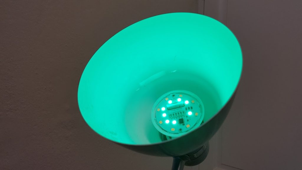
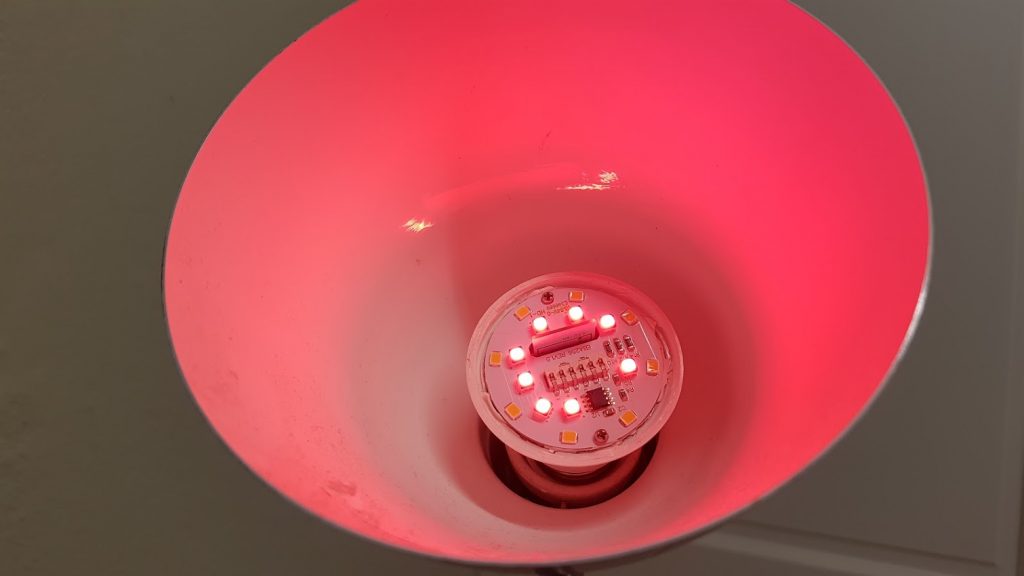
#and then some fun : Set the colour to red :
Color ff00000000
#green
Color 00ff000000
#blue
Color 0000ff0000
#white
Color 000000ff00
# all on - it's damn bright
Color ffffffff00
# These allow HA to auto-detect the device - but you'll need to upgrade from the basic to classic firmware first.
SetOption19 1
SetOption31 1
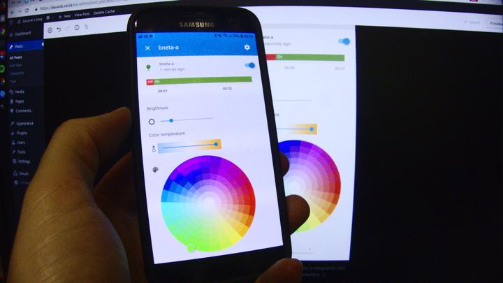
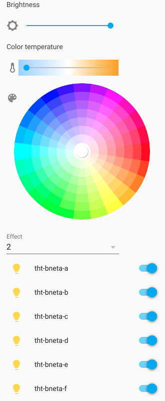
Of course the real benefit of all this is integration into Home Assistant’s web interface 🙂 Now I can script the lights as part of a larger network of devices… think continuously adjusting house lighting based on presence and current exterior lighting conditions.
Controlling groups of lights.
And that’s about that. Hopefully this helps someone 🙂